
Transformer Fire and Blast Proof Walls: 4-Hour Steel Composite Fire Barriers
Wedge Industries Limited designs, supplies and installs transformer fire and blast proof walls built from WedgeSCB high-impact steel composite boards — a fibre-reinforced calcium silicate and cement core bonded between perforated galvanised steel faces. Fire resistance up to 240 minutes, Class A1 non-combustible, impact-tested to BS EN 1128, and erected as free-standing barriers up to 10 m × 9 m between oil-filled transformers, in substations, power plants and industrial buildings across India and 45+ export markets.
Supply only or supply + install · Meets the 4-hour baffle-wall requirement for oil-filled transformers under the CEA Safety Regulations · Part of the Wedge passive fire protection range
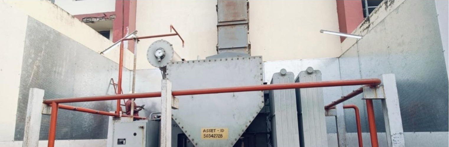
What is a transformer fire and blast proof wall?
A transformer fire and blast proof wall is a free-standing, non-combustible barrier erected between an oil-filled transformer and the next transformer, building or plant item, so that a tank rupture, oil fire or explosion in one unit cannot spread to its neighbour. It must survive a hydrocarbon-type fire for the rated period (typically 2–4 hours), resist flying debris and pressure from a tank failure, and stand up to weather without maintenance for the life of the substation.
Indian regulations treat this as a fire-separation problem: where oil-filled transformers cannot be spaced far enough apart, a baffle wall of 4-hour fire rating is required between them. Conventional answers are thick RCC or brick walls, which are slow to build, need foundations sized for their own weight, and cannot be moved when the switchyard is extended. Wedge builds the same 4-hour barrier as a lightweight steel-framed wall clad in 9.5 mm WedgeSCB boards — 21–23 kg/m² instead of 400–500 kg/m² for 200 mm concrete — installed in days on a strip footing or on existing plinths.
How a Wedge transformer fire wall is built
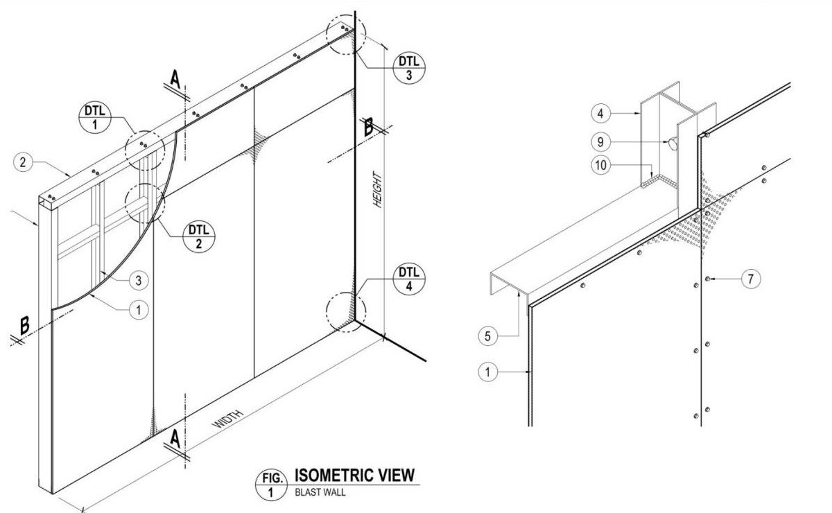
| # | Component | Specification in the Wedge design |
|---|---|---|
| 1 | Vertical boards | WedgeSCB 9.5 mm steel composite board, 1200 × 2400 mm, joints at 600 mm centres |
| 2 | Top cross beam | Structural steel section sized to wall height and wind / blast load (schedule on sheets 2 & 3) |
| 3, 4 | Vertical members | Steel channel / I-section posts at board-joint centres, bolted to base and beam |
| 5 | Horizontal members | Steel channels at nominal 1500 mm centres |
| 6 | Connectors | Steel L-angle connectors at beam-to-post junctions |
| 7 | Board fixing | 5.5 mm Ø self-drilling screws at nominal 150 mm centres |
| 8 | Base fixing | M10 anchor bolts at nominal 500 mm centres into the concrete base or wall |
| 9, 10 | Frame connections | M12 bolts and nuts; site welding where detailed |
| 11 | Substrate | Concrete strip footing, plinth or existing RCC wall |
The frame carries the wind and blast load; the boards provide the fire, heat and impact barrier. Single-skin 9.5 mm boards give a 2–4 hour barrier depending on the tested configuration; a double-skin or board-plus-mineral-wool build-up is used where the insulation criterion (temperature rise on the unexposed face) governs, for example next to a control room or cable trench. Wedge issues the frame schedule, section drawings and a load calculation for each wall height and site wind zone.
WedgeSCB steel composite board — the fire and blast wall material
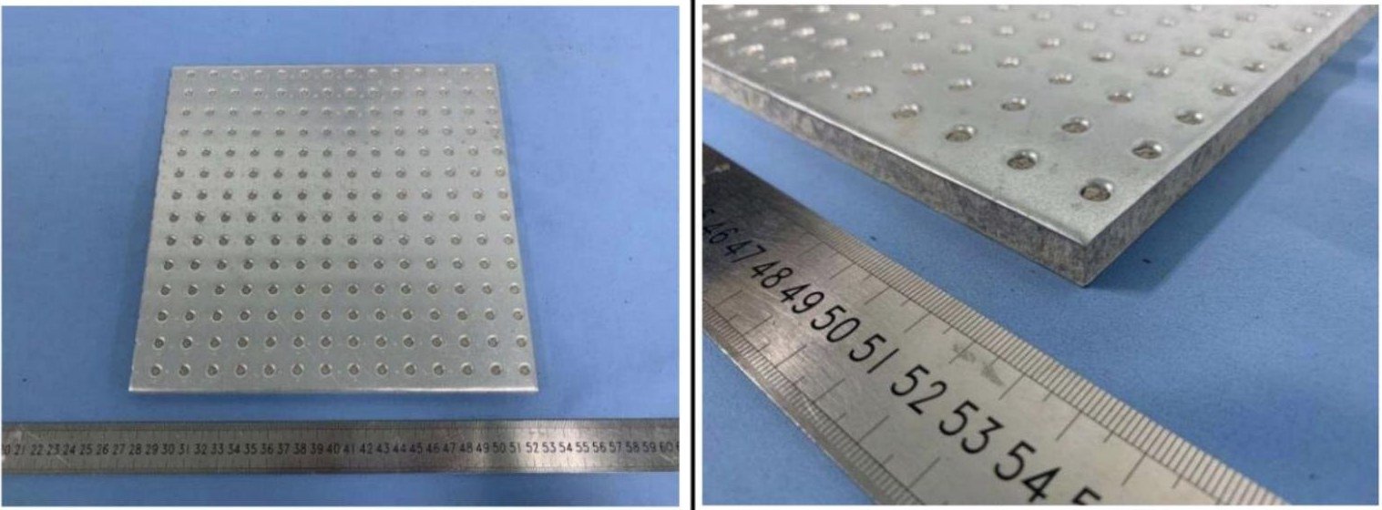
WedgeSCB is a heavy-duty composite board: a fibre-reinforced, high-density calcium silicate and cement core with 0.5 mm perforated galvanised steel sheets mechanically bonded to both faces — the perforations key the steel into the core so the board behaves as one plate under impact. It is fire resistant up to 240 minutes and non-combustible to BS 476: Part 4, BS EN 1716 and BS EN 1182 (Euroclass A1 / A1FL), with fire-resistance evidence to BS 476: Part 22 and BS 476: Parts 20–24 / BS EN 1364-1 & 2, and up to 3 hours as a hydrocarbon fire barrier.
- Waterproof, shockproof, tasteless and non-toxic; does not rot, crack or deform outdoors
- Very high mechanical strength — bending 84–109 N/mm², compressive 60 N/mm²
- Continuous service 400 °C, short-term up to 1000 °C
- Cuts and drills with standard tools; screw-fixed to steel framing
- Asbestos-free; MSDS available (cementitious core, pH 12, inert and non-flammable)
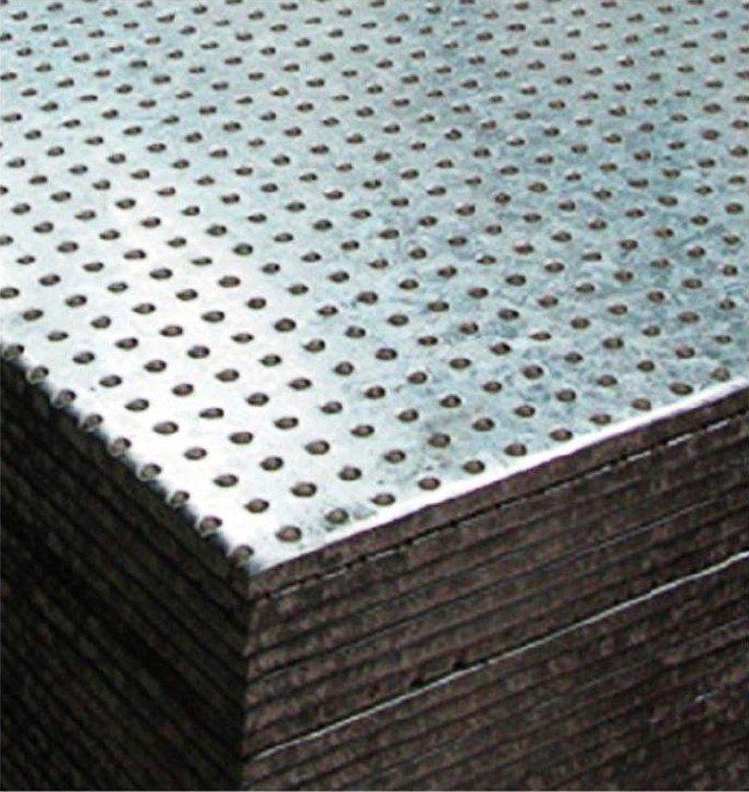
WedgeSCB technical specification
| Property | Unit | WedgeSCB 6 | WedgeSCB 9.5 |
|---|---|---|---|
| Continuous service temperature | °C | 400 | 400 |
| Short-term service temperature | °C | 1000 | 1000 |
| Bulk density | kg/m³ | 2800 | 2210 |
| Compressive strength | N/mm² | 60 | 60 |
| Bending strength | N/mm² | 109 | 84 |
| Tensile strength | N/mm² | 32 | 30 |
| Modulus of elasticity | N/mm² | 55,000 | 40,000 |
| Thermal conductivity λ | W/m·K | 0.55 | 0.55 |
| Sound insulation | dB | 28 | 30 |
| Board weight | kg/m² | 16.8 | 21 |
| Humidity content | % | 6 | 6 |
| Water absorbency | % | 14 | 14 |
| Standard board size | mm | 1200 × 2400 | |
| Fire resistance | min | Up to 240 (BS 476-22 / BS EN 1364); up to 180 hydrocarbon | |
| Reaction to fire | — | Non-combustible, Euroclass A1 / A1FL | |
Values from the WedgeSCB technical data sheet and the Blast Proof Wall Boards certificate of analysis. A signed COA is issued with every supply.
Third-party test results — Intertek report 201120193GZU-001
| Test | Method | Result |
|---|---|---|
| Reaction to fire | BS EN 13501-1:2018 (ISO 1182 + ISO 1716) | Class A1 — temperature rise 5.7 °C (limit 30), sustained flaming 0 s, mass loss 18.6 % (limit 50), gross heat of combustion 0.8 MJ/kg (limit 2.0) |
| Impact resistance | BS EN 1128:1996, 4.5 kg hemispherical striker | No holes or cracks at 1750 mm drop height; impact resistance IR > 164 |
| Bending strength (MOR) | EN 12467 cl. 7.3.2, 200 mm span | 48.44 MPa average — Class 5 (highest class); MOE 13,561 MPa |
| Apparent density | EN 12467 cl. 7.3.1 | 2.23 g/cm³ |
| Thermal conductivity | ASTM C518-17 | 0.122 W/m·K |
| Moisture content | ASTM C1185-08 | 4.98 % |
| Dimensional stability | EN 318:2002, 30–85 % RH cycling | 0.2 mm/m length change, 0.3 % thickness change |
| Specimen | — | 1200 × 2400 × 9.5 mm; 0.5 mm steel each face, 8.5 mm fibre-cement core, 23 kg/m² |
Regulations: CEA, NBCS 2026 and international codes for transformer fire walls
Transformer fire separation in India is governed by the electricity safety regulations first, and by the building code second. Wedge walls are designed to satisfy both, plus the IEEE / NFPA and IEC practice that international EPC contractors and insurers specify.
| Code | What it requires | How the Wedge wall satisfies it |
|---|---|---|
| CEA (Measures relating to Safety and Electric Supply) Regulations, 2010 — Reg. 44 | Where an oil-filled transformer or apparatus holds more than 2,000 litres of oil, provision must be made to prevent the spread of fire — including baffle walls of 4-hour fire rating between the apparatus where adequate clearance is not available, and oil soak pits / drainage | WedgeSCB build-ups rated to 240 minutes; wall extends above the conservator and beyond the radiators so the 4-hour line is continuous |
| CEA Technical Standards for Construction of Electrical Plants and Electric Lines, 2010 | Transformers in substations to be separated from one another by fire walls where the specified clearances cannot be met | Free-standing steel-framed walls to any bay layout, including retrofit between existing units |
| NBCS 2026, Part F — Fire & Life Safety (successor to NBC 2016 Part 4) | Performance-based framework: substations and transformer areas are fire compartments separated from occupied buildings by fire-resisting construction; oil-filled transformers segregated with fire-resisting walls or clearances; compliance shown by tested assemblies | Non-combustible A1 boards with BS 476-22 / BS EN 1364 evidence; see the NBCS 2026 vs NBC 2016 guide and Part F checklist |
| NFPA 850 / IEEE 979 (power plant & substation practice) | Fire barrier of at least 2-hour rating between adjacent oil-insulated transformers when separation is below the recommended distance; barrier to extend at least 0.3 m above the top of the tank and conservator and 0.6 m beyond the transformer and radiators | Wall height and length set from the transformer envelope; 2-hour and 4-hour configurations available |
| IEC / BS EN 61936-1 — Power installations above 1 kV | Fire walls EI 60 to EI 90 (indoor) or separation distances from 3 m to 15.2 m by liquid volume; fire walls where the distance cannot be achieved | EI ratings met with single- or double-skin WedgeSCB build-ups; Euroclass A1 material |
| BS 476: Parts 4, 20–24 · BS EN 1364-1 & 2 · EN 13501-1 | Non-combustibility, fire resistance of non-loadbearing walls, reaction-to-fire classification | WedgeSCB test basis; Intertek A1 classification report supplied with the offer |
Wall height, length and stand-off are fixed by the transformer envelope and the code the project follows — send the transformer GA drawing and bay layout and Wedge will size the wall to the CEA 4-hour requirement or the NFPA 850 envelope, whichever governs.
Where transformer fire and blast proof walls are used
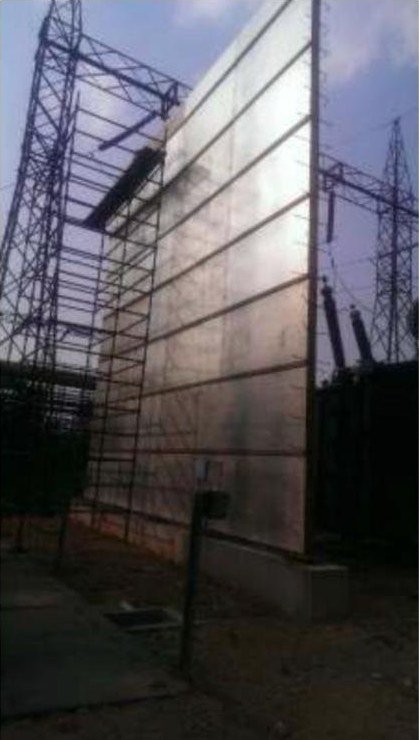 Steel plant
Jindal Steel & Power, Raigarh
10 m × 9 m free-standing transformer barrier wall between generator transformers — steel frame on a strip footing, 9.5 mm WedgeSCB cladding, built alongside live switchyard equipment.
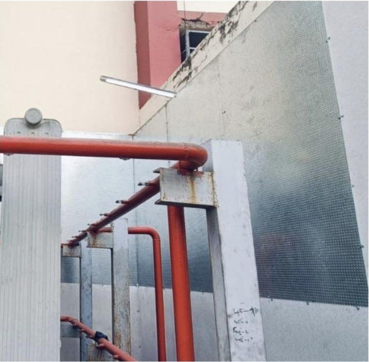 Retrofit
Industrial transformer bays
Fire walls retro-fitted between existing distribution transformers and the plant building, working around fire-water rings, cable trenches and radiators with no shutdown of the adjacent unit.
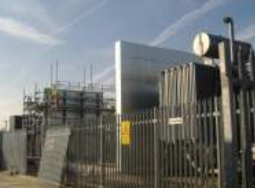 Export
Utility substations
Compact steel-composite fire barriers for 33–400 kV substations where land is tight and the NFPA / IEC separation distances cannot be met — supplied to utilities and EPC contractors in India and overseas, and offered across the Gulf and Africa.
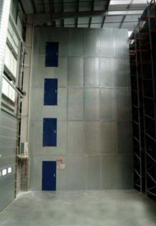 Compartment wall
Fire walls with fire doors
Full-height 4-hour compartment walls inside warehouses and process halls, with Wedge fire-rated doors and fire door components in the same tested line.
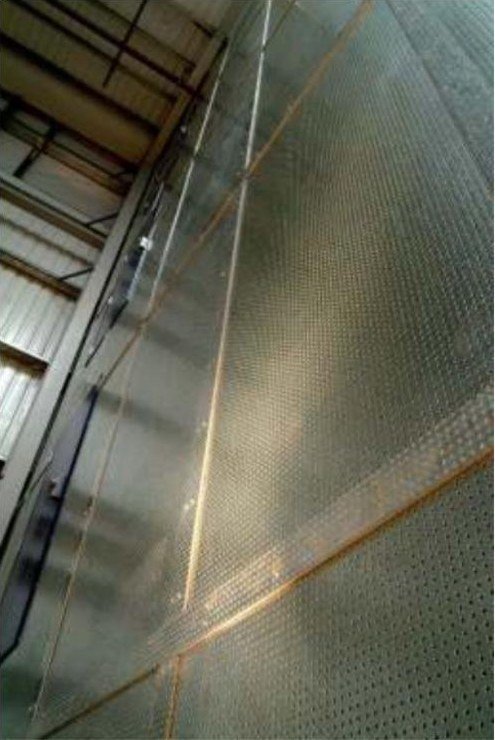 Hazardous areas
Blast-resistant enclosures
Hydrocarbon fire barriers, hazardous-material vaults, battery and BESS container separation, hoardings for oil & gas and petrochemical plants — see EV battery and thermal-runaway fire barriers.
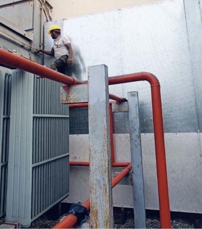 Turnkey
Supply and installation
Wedge crews survey, fabricate the steel frame, fix the boards, seal joints and hand over with the material COA, Intertek report and as-built drawings — across Delhi NCR, Uttar Pradesh, Chhattisgarh and pan-India.
Applications of WedgeSCB steel composite boards
Transformer fire wall vs RCC wall vs brick wall
| Criterion | Wedge steel composite fire wall | 200 mm RCC wall | 230 mm brick wall |
|---|---|---|---|
| Fire rating | Up to 240 min as a tested, non-combustible assembly | Typically 2–4 h, depends on cover and spalling | Typically 2–4 h; mortar joints crack under thermal shock |
| Impact / blast debris | Steel-faced board, no holes at 1750 mm / 4.5 kg drop; steel frame designed to project blast load | Good, but spalls; heavy reinforcement needed | Poor — masonry fragments become secondary debris |
| Weight | 21–23 kg/m² boards + frame | ≈ 480 kg/m² | ≈ 400 kg/m² |
| Foundation | Strip footing / anchors into existing plinth | Heavy footing, shuttering, curing | Footing plus RCC bands |
| Time on site | Days; dry construction, no curing | Weeks including curing | Weeks |
| Working next to live equipment | Bolted assembly, minimal wet trades and dust | Concrete pumping and formwork in the bay | Wet trades in the bay |
| Relocation / extension | Demountable and re-usable | Demolition | Demolition |
| Weathering | Galvanised steel faces, cement core — no paint or render | Needs anti-carbonation coating | Needs render and paint |
Transformer fire wall price
A transformer fire and blast proof wall is priced per square metre of wall face, in ₹ for India and $ for export, against three inputs: the board build-up (single or double skin 9.5 mm WedgeSCB), the steel frame schedule (wall height, wind zone and blast load) and the scope — boards only, boards plus fabricated frame, or supply-and-install with footing. Because frame steel is the largest variable, quotations are issued from the transformer GA drawing rather than from a rate card. Send the transformer envelope (tank height with conservator, radiator width), the number of bays and the site location; Wedge replies within one working day with a bill of quantities and a firm price. Wedge also supplies blast proof wall boards alone to EPC contractors erecting their own frames.
Installation of a Wedge transformer fire wall
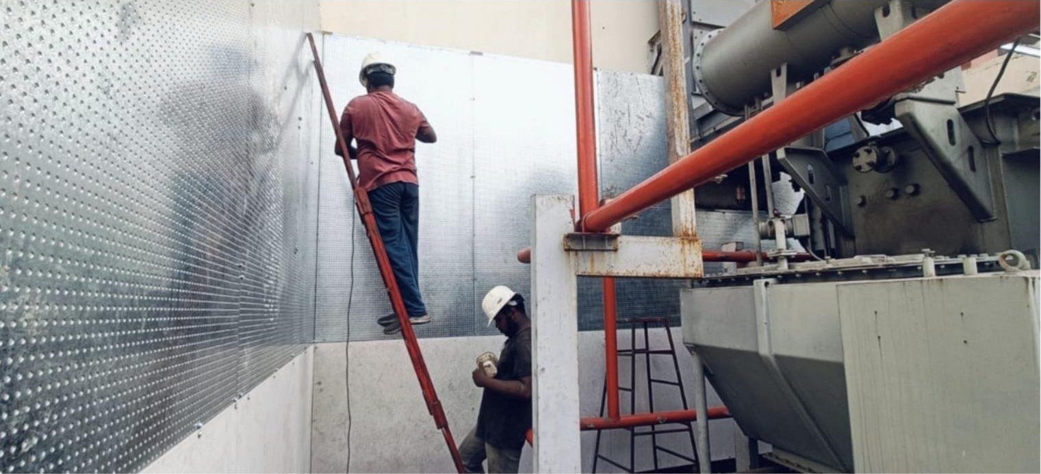
- Survey and design — transformer envelope, oil volume, bay layout, wind zone and any blast-load brief; Wedge issues the frame schedule and section drawings.
- Foundation — concrete strip footing or M10 anchors at 500 mm centres into the existing plinth or RCC wall.
- Steel frame — vertical members at board-joint centres, horizontal members at 1500 mm centres, top cross beam; M12 bolted L-angle connections, welded where detailed.
- Boards — 9.5 mm WedgeSCB fixed vertically with 5.5 mm self-drilling screws at 150 mm centres, joints at 600 mm centres over a steel member.
- Joints and edges — fire-rated sealant or cover strips at board joints and at the base; the wall runs at least 0.3 m above the conservator and 0.6 m beyond the radiators unless the project code sets more.
- Hand-over — as-built drawings, WedgeSCB COA, MSDS and the Intertek classification report for the fire officer’s file.
Boards are cut with dust extraction and standard tools; no hot work is needed on the boards themselves. Where the wall also has to attenuate noise, a mineral wool infill between two board skins adds acoustic performance to the fire rating.
Related fire protection products
Send your transformer bay drawing
Attach the transformer GA drawing or a site photo with dimensions, tell us the oil volume, number of bays and location, and whether you need supply only or supply-and-install. We reply within one working day with the wall design, BOQ and a price in ₹ and $.
Transformer fire and blast proof wall FAQs
When is a fire wall between transformers mandatory in India?
Under Regulation 44 of the CEA (Measures relating to Safety and Electric Supply) Regulations 2010, where an oil-filled transformer or apparatus holds more than 2,000 litres of oil and adequate clearance between units is not available, baffle walls of 4-hour fire rating must be provided between the apparatus, along with oil soak pits. The CEA construction standards and NBCS 2026 Part F carry the same principle: separate oil-filled transformers from each other and from buildings by distance or by fire-resisting walls.
What fire rating does a transformer fire wall need?
Four hours to meet the CEA baffle-wall requirement in India; at least two hours under NFPA 850 / IEEE 979 practice; EI 60 to EI 90 for indoor installations under IEC 61936-1. WedgeSCB steel composite boards are fire resistant up to 240 minutes and non-combustible Class A1, so one material covers all three regimes.
How high and how long should the wall be?
Follow the transformer envelope: the wall should extend at least 0.3 m above the top of the tank and conservator and at least 0.6 m beyond the transformer and its radiators on each side (NFPA 850 practice), or as the project fire consultant specifies. Wedge has built free-standing walls up to 10 m × 9 m; taller walls are designed with heavier frame sections.
Is a steel composite fire wall really blast proof?
The board is impact-rated — no holes or cracks at a 1750 mm drop with a 4.5 kg striker (BS EN 1128), bending strength Class 5 to EN 12467 — and the perforated steel faces hold the core together under debris strike. Blast pressure resistance is a property of the whole wall, so the steel frame is sized for the project’s design pressure by Wedge’s engineers; the boards themselves are the same in every configuration.
How does it compare with an RCC transformer fire wall?
A Wedge wall weighs about 21–23 kg/m² plus frame against roughly 480 kg/m² for 200 mm concrete, needs only a strip footing or anchors, goes up in days without curing, and can be dismantled and re-used when the switchyard is extended. Both achieve a 4-hour rating; the steel composite wall does not spall or crack under thermal shock.
What documents are supplied with the wall?
The WedgeSCB technical data sheet, the signed certificate of analysis for the batch, the material safety data sheet, the Intertek test report 201120193GZU-001 (Class A1, impact, bending, density, thermal conductivity), the design drawings with frame schedule and, for installed walls, as-built drawings.
Need a 4-hour transformer fire wall that goes up in days?
Send the transformer drawing and bay layout — Wedge will design the wall to CEA / NBCS 2026 / NFPA 850, quote in ₹ and $, and supply or install it.